Apartment, Multifamily & Rental Property Access Control
Apartment building access control hardware: anti-clone readers with matched fob sets, QR visitor codes, 4G controllers for rentals and UHF tags for gates.
Send us your controller model, card type and install environment. We'll shortlist compatible hardware and quote within 24 hours.
12 V DC, 3 A linear power supply for access control doors, with PUSH and CONTROL inputs and NC/NO lock outputs. Gray steel case, 220 V AC input.
PW-120 is the 3 A version of our 12 V DC linear access control supply. It powers locks, readers and intercom panels, and it can switch a lock on its own: an exit button connects to the PUSH input, an access controller can drive the CONTROL input with a ±5 to ±15 V signal, and separate NC and NO outputs suit fail-safe and fail-secure locks.
The linear design holds ripple to 100 mV or less, which keeps the supply quiet for readers and intercom audio. It sits in a 182 × 79 × 62 mm gray steel case and runs from –20 to +50 °C. If a load is too high or the wiring is shorted, a self-resetting protective element cuts the output; after the fault is removed and the element has cooled for roughly 10 minutes, the supply restarts normally.
Input is 220 V AC ±20%, so PW-120 is intended for 220–240 V mains; sites on 110/120 V should use the PW-130 enclosure, which accepts 100–260 V AC. There is no battery charging circuit. Choose PW-110 when the same design needs a 5 A rating.
The NC/NO lock terminals deliver an unregulated 17 V, with the C/NO contact rated for 1.5 A; the regulated DC 12 V terminal is rated for 1.2 A. Confirm that each lock tolerates the NC/NO terminal voltage, add up every device on the supply, and keep 25–50% headroom.
| Input voltage | 220 V AC ±20% |
|---|---|
| Output voltage | 12 V DC ±15% |
| Rated output current | 3 A |
| Ripple | ≤ 100 mV |
| Topology | Linear |
| NC / NO lock outputs | 17 V, unregulated |
|---|---|
| Lock contact (C/NO) load | 1.5 A max |
| DC 12 V output load | 1.2 A max |
| PUSH input | Switch signal (exit button) |
| CONTROL input | ±5 V to ±15 V signal |
| Overload / short circuit | Output shuts off; resumes once the fault is cleared and the protective element has cooled (about 10 minutes) |
|---|---|
| Dedicated over-current protection (OCP) circuit | No |
| Battery charging | None |
| Standard battery | None |
| Housing | Steel, gray |
|---|---|
| Dimensions | 182 × 79 × 62 mm |
| Operating temperature | –20 to +50 °C |
| Parameter | PW-110 | PW-120 |
|---|---|---|
| Rated output current | 5 A | 3 A |
| Output voltage | 12 V DC ±15% | 12 V DC ±15% |
| Input voltage | 220 V AC ±20% | 220 V AC ±20% |
| Ripple | ≤ 100 mV | ≤ 100 mV |
| Lock contact (C/NO) load | 1.5 A max | 1.5 A max |
| DC 12 V terminal load | 1.2 A max | 1.2 A max |
| Battery charging | None | None |
| Case | Steel, gray, 182 × 79 × 62 mm | Steel, gray, 182 × 79 × 62 mm |
Both units share the same case, inputs and terminal ratings; only the rated output current differs.
Specifications can change between production batches. Confirm the current revision with us before placing volume orders.
Quote the SKU that matches your frequency, interface and mounting. Not sure? Send us your controller model and we will pick the variant for you.
| SKU | Configuration | Actions |
|---|---|---|
| PW-120 | 12 V DC 3 A linear access control power supply, 220 V AC input, gray steel case |
Apartment building access control hardware: anti-clone readers with matched fob sets, QR visitor codes, 4G controllers for rentals and UHF tags for gates.
Only the rated output current: PW-120 is rated 3 A and PW-110 is rated 5 A. Case, inputs and terminal ratings are the same.
No. It needs 220 V AC ±20%. For 110/120 V installations, use the PW-130 power box, which accepts 100–260 V AC.
Use the output that removes power when the exit button or controller signal operates, normally the NC terminal for fail-safe locks. Check the lock accepts the 17 V unregulated terminal voltage.
No. There is no charging circuit; use an upstream UPS or the PW-130 enclosure with its optional battery where backup is required.
Maglock wiring with dry-relay COM/NC: keypad and reader diagrams, REX signals, approved egress release paths and manufacturer-specific suppression.
A fail-safe lock releases when power is cut; a fail-secure lock stays locked. Learn which to use per door, how to wire NO/NC, and what egress codes expect.
Program a standalone access control keypad: enter programming mode, change the master code, add card and PIN users, set relay time, reset and wire it.
12 V DC, 5 A linear power supply with exit-button and control inputs and NC/NO lock outputs, in a 182 × 79 × 62 mm steel case. 220 V AC input.
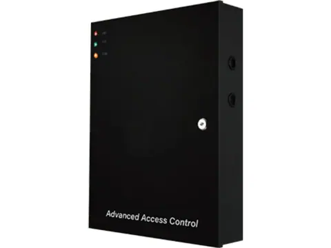
450 × 340 × 90 mm steel power box with a 12 V DC 5 A or 10 A supply, circuit breaker, tamper switch and lid-activated LED. Optional backup battery.
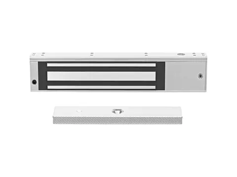
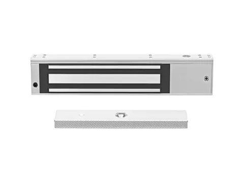
Single-door 280 kg (600 lb) maglock with NO/NC status output, a 250 × 47 × 26 mm aluminum-alloy body and a 12 or 24 V DC coil drawing 480/240 mA.
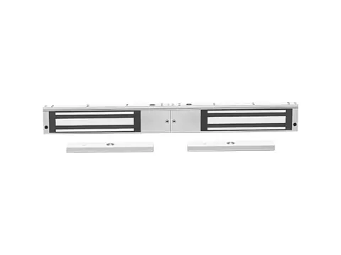
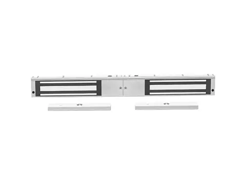
One 500 mm aluminum body holding two 280 kg (600 lb) magnets for double doors, with an NO/NC status signal output and 12 or 24 V DC operation.
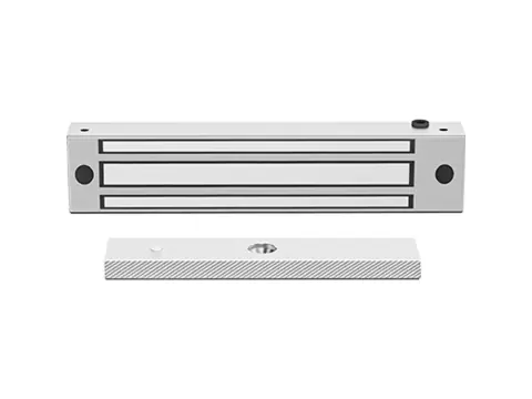
Waterproof single-door maglock holding 280 kg (600 lb), with an aluminum-alloy housing, installer-selectable 12/24 V DC coil and a door-status output.
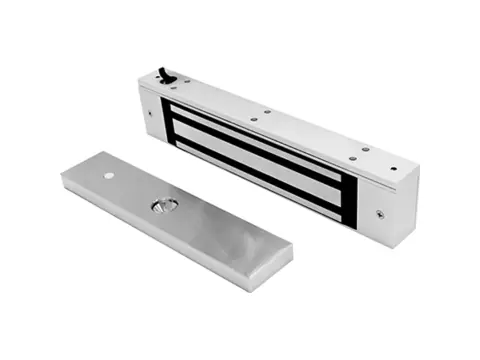
Fail-safe 280 kg (600 lb) single-door maglock with a 250 × 47 × 26 mm aluminum-alloy body, 12 or 24 V DC coil (480/240 mA) and hex-socket screws.
Fail-safe double-door maglock: two 280 kg (600 lb) magnets in one 500 × 47 × 26 mm aluminum body, 12 or 24 V DC, without signal output.
Compact 210 mm stainless-steel maglock with 280 kg (600 lb) holding force, waterproof construction, selectable 12/24 V DC coil and a door-status output.
Send your card type, interface and quantity. You get a quote, lead time and compatibility notes within 24 hours — samples available for most items.