Key takeaways
- Wiegand 26-bit (H10301) = 1 even parity bit + 8-bit facility code (0–255) + 16-bit card number (0–65,535) + 1 odd parity bit.
- Combined value = facility code × 65,536 + card number; in 6-digit hex, the first two digits are the facility code and the last four the card number.
- The 10-digit number printed on an EM card (8H10D) matches 32-bit output; the 'xxx,xxxxx' number matches 26-bit facility code and card number.
- Reader and controller must use the same bit length and layout; a 34-bit reader will not work on a port set to 26-bit until one side is reconfigured.
- 26-bit leaves only 65,536 card numbers per facility code, so check new cards against enrolled numbers before issuing them.
Wiegand calculator
Standard H10301 layout: 26-bit = even parity + 8-bit facility code + 16-bit card number + odd parity. 34-bit shown as even parity + 16-bit high word + 16-bit low word + odd parity (the common 32-bit UID layout). Some controllers use proprietary layouts — confirm with your panel documentation.
The Wiegand 26-bit format (often referred to as H10301) sends 26 bits per card read: an even parity bit, an 8-bit facility code (0–255), a 16-bit card number (0–65,535) and an odd parity bit. Because it carries only 24 data bits, the number a controller shows often differs from the number printed on the card. Use the calculator above to convert between facility code, card number, decimal and hex; the sections below explain the bit map, the other common formats and how to order cards that match.
Bit map: parity bits, facility code and card number
A Wiegand reader sends bits on two data lines, D0 and D1, both normally held high (typically at 5 V). A short low pulse on D0 is a 0 and a short low pulse on D1 is a 1. The SIA AC-01 Wiegand standard allows pulse widths of 20–100 µs with 200 µs to 20 ms between pulses, and bits are sent most-significant first. The link is one-way and unencrypted. For terminals, cable and grounding, see how to wire a Wiegand card reader.
The 26 bits are laid out as follows:
| Bit position | Field | Length | Value range | Rule |
|---|---|---|---|---|
| 1 | Even parity | 1 bit | 0 or 1 | Bits 1–13 together contain an even number of 1s |
| 2–9 | Facility code | 8 bits | 0–255 | Most significant bit first |
| 10–25 | Card number | 16 bits | 0–65,535 | Most significant bit first |
| 26 | Odd parity | 1 bit | 0 or 1 | Bits 14–26 together contain an odd number of 1s |
The parity bits do not line up with the fields. The leading parity bit covers the 8 facility-code bits plus the top 4 bits of the card number; the trailing parity bit covers the lower 12 bits of the card number. A controller that finds either parity wrong discards the read.
Worked example: facility code 123, card number 45678.
- Facility code 123 in binary:
01111011 - Card number 45678 in binary:
1011001001101110 - Bits 2–13 are
011110111011, which contains nine 1s, so the even parity bit is 1 (making ten). - Bits 14–25 are
001001101110, which contains six 1s, so the odd parity bit is 1 (making seven). - Full frame:
1 01111011 1011001001101110 1, which is 2F764DD in hex. The 24 data bits alone are 7BB26E.
The format allows 256 facility codes × 65,536 card numbers, or 16,777,216 combinations in total. There is no central registry for facility codes in the open 26-bit format, so two card suppliers can issue the same facility code and card number. Duplicates between sites, or inside a mixed batch of cards, are a real possibility.
Wiegand 26 vs 34 vs 37-bit and custom formats
Bit length alone does not identify a format. Several different 34-, 35- and 37-bit layouts are in use, and the controller must be told which one to expect. The most common are:
| Format | Total bits | Parity bits | Facility or site field | Card number field | Card numbers per site code | Notes |
|---|---|---|---|---|---|---|
| 26-bit (H10301) | 26 | 2 | 8 bits (0–255) | 16 bits (0–65,535) | 65,536 | Open format, the most widely supported |
| 34-bit, common layout (also H10306) | 34 | 2 | 16 bits (0–65,535) | 16 bits (0–65,535) | 65,536 | Often used to carry a 4-byte (32-bit) card UID |
| 35-bit corporate format | 35 | 3 | 12-bit company ID (0–4,095) | 20 bits (0–1,048,575) | 1,048,576 | Proprietary; numbers allocated per end customer |
| 37-bit with facility code (H10304) | 37 | 2 | 16 bits (0–65,535) | 19 bits (0–524,287) | 524,288 | Larger number space than 26-bit |
| 37-bit, no facility code (H10302) | 37 | 2 | None | 35 bits | Not applicable | Card number only |
In the common 34-bit layout, bit 1 is even parity over bits 2–17 and bit 34 is odd parity over bits 18–33. When a 13.56 MHz reader uses 34-bit to send a 4-byte UID, the “facility code” is simply the upper 16 bits of the UID, not a site code anyone assigned.
Which to choose? Use 26-bit when the controller or the installed cards require it. Use 34-bit when passing 13.56 MHz UIDs, because 26-bit drops a byte and makes duplicate numbers more likely. Some readers also offer longer frames for 7-byte UIDs, but controller support for those varies, so check before you specify.
Using the calculator: facility code and card number to hex and back
The calculator above works in both directions for 26-bit and the common 34-bit layout:
- Choose 26-bit or 34-bit.
- Enter a facility code and card number to see the full bit string with both parity bits, the combined decimal value and the hex value.
- Or paste a combined decimal value (such as a 10-digit number) or a hex value to split it back into facility code and card number.
The same arithmetic works by hand:
- Combined decimal = facility code × 65,536 + card number. For example, 123 × 65,536 + 45,678 = 8,106,606.
- Split a combined value: facility code = whole part of value ÷ 65,536; card number = the remainder. 8,106,606 ÷ 65,536 = 123, remainder 45,678.
- Wiegand to hex: the 24 data bits are 6 hex digits. The first two are the facility code (7B = 123) and the last four are the card number (B26E = 45678).
- Full-frame hex: some logs and analyzers show all 26 bits including parity (2F764DD in the example). Don’t confuse this with the 6-digit data value.
For 34-bit, the 32 data bits are 8 hex digits: the first four are the upper 16-bit field and the last four the lower 16-bit field. If your controller uses a different 34-bit layout, check its documentation before relying on the split.
Why the number printed on a card differs from the panel reading
When a card works at the door but the number on screen doesn’t match the number on the card, it is usually one of these:
- Different slice of the chip ID. A reader in 26-bit mode sends only the low 24 bits of an EM card’s ID, and 34-bit mode sends the low 32 bits. The number printed on the card may be based on either, or on the full 40 bits.
- Different view of the same bits. Controllers may show the card number only (45678), facility code and card number (123 and 45678), or the combined 24-bit value (8106606).
- Decimal versus hex. 45678 and B26E are the same card number.
- Byte order on 13.56 MHz UIDs. A UID of A1 B2 C3 D4 reads as 2,712,847,316 when sent most-significant byte first, and 3,569,595,041 when a reader reverses the byte order (D4 C3 B2 A1).
- Leading zeros. 0008106606 and 8106606 are equal as numbers, but software that compares text will treat them as different.
- Facility code not printed. On some prox-style cards only the card number is printed, and the facility code appears on the packaging or order paperwork.
If the reader and controller disagree on format, you usually get no read at all: a 34-bit frame on a port set to 26-bit fails the bit-count or parity check, or the panel decodes the wrong bits. The reliable fix is to enroll cards by presenting them at a reader connected to the controller, or to convert the printed number with the calculator before typing it in.
EM4100 10-digit, 8H10D and decimal conversions
An EM4100 card holds 40 data bits, usually written as 10 hex digits: an 8-bit version or customer field followed by a 32-bit ID. Card suppliers print one or two numbers derived from it, and desktop readers and software use short labels such as “8H10D” (the last 8 hex digits shown as a 10-digit decimal). Here is one example card, ID 3C1A7BB26E, shown every common way:
| Label | Bits used | How it is formed | Example value |
|---|---|---|---|
| Full ID (10 hex digits) | 40 | Version byte + 32-bit ID | 3C1A7BB26E |
| 10H13D | 40 | All 10 hex digits as a 13-digit decimal | 0258142351982 |
| 8H10D (10-digit number printed on many cards) | Low 32 | Last 8 hex digits as a 10-digit decimal | 0444314222 |
| 34-bit output, split 16/16 | Low 32 | Upper and lower 16 bits in decimal | 6779 and 45678 |
| 6H8D | Low 24 | Last 6 hex digits as an 8-digit decimal | 08106606 |
| 26-bit output (often printed as “123,45678”) | Low 24 | 8-bit facility code and 16-bit card number | 123 and 45678 |
Two rules follow from the table:
- The 10-digit printed number matches a reader set to 34-bit output, when the controller displays the full 32-bit value.
- The “xxx,xxxxx” printed number matches 26-bit output. You cannot recover the 10-digit number from a 26-bit read, because the top 8 bits of the 32-bit ID are dropped. In the example, 26-bit output gives 8,106,606, not 444,314,222.
USB desktop readers type one of these conversions as keystrokes, selectable on many models. Our guide to USB RFID reader output formats shows how to match them to your software.
Setting the output format on readers and keypads
The format has to match at both ends of the cable.
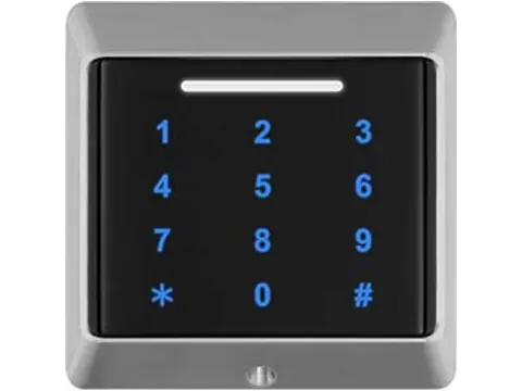
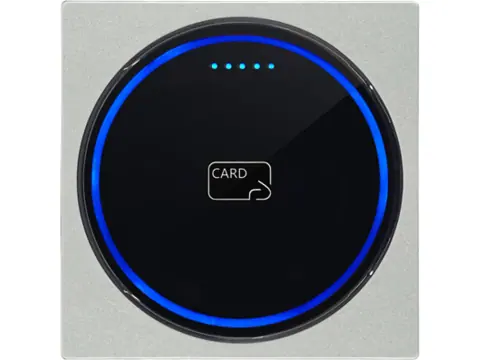
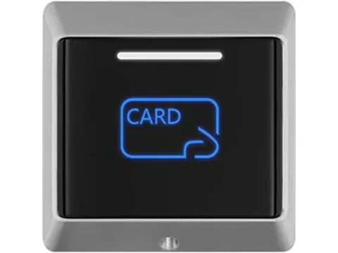
- Readers. Wiegand output length is set by DIP switch, jumper, configuration card, PC utility or at the time of order, depending on the model. Wiegand card and keypad readers commonly offer 26- and 34-bit output; confirm which layouts a model supports before you order.
- Controllers. Each reader input is set to a format. Some controllers detect the bit count automatically, but they still need to know the layout to split the facility code from the card number.
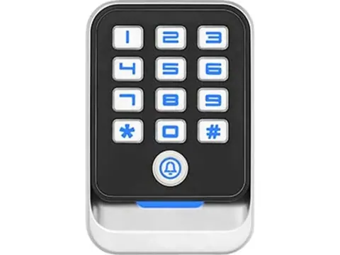
- Keypads. PIN entry is sent in its own format: 4 bits per key, 8 bits per key (the key value plus its complement, for error checking), or, on some keypads, the whole PIN buffered and sent as a single 26- or 34-bit frame when # is pressed. The controller must be set to the same keypad mode.
- Standalone keypads with Wiegand in and out. When a keypad controller accepts an external reader, or acts as a reader for a panel, both directions must use the same bit length.
- OEM modules. Embedded 125 kHz reader modules may provide Wiegand, UART or both. Check the output options on the datasheet of the exact variant you order.
Wiegand itself has no encryption or supervision, so anyone with access to the cable can capture or replay card numbers. If that matters for your site, compare it with an encrypted, bidirectional interface in Wiegand vs OSDP.
Ordering replacement cards in the right format
New cards must match what the controller already expects, not just the frequency. EM4100 IDs are fixed when the chip is programmed, so you usually cannot pick a facility code for an EM card after the fact. Instead, ask for sequential numbering, a starting number or a printed number range, and check the delivered range against enrolled users before issuing. With 26-bit output only 24 of the 32 ID bits are used, so two different EM cards can present the same number.
Cards in a proprietary, end-user-allocated format may only be available through the format owner’s authorized channel. Confirm this before you plan a re-order.
Checklist for a replacement order:
- Technology and frequency: 125 kHz EM4100, 125 kHz prox-style or 13.56 MHz (see 125kHz vs 13.56MHz if you are not sure)
- Bit format and layout: 26-bit, 34-bit or another, and which layout for that length
- Facility code in use, for 26-bit and prox-style systems
- Card number range already enrolled, so the new batch does not duplicate it
- Printed number format wanted: 10-digit, “xxx,xxxxx”, both, or none
- Form factor: ISO card, clamshell, key fob or wristband
- A sample card or photo of an existing card, and the controller model
- A sample read on your own controller before the bulk order ships
You can browse cards, key fobs and wristbands by frequency and chip once you have these details.
Next steps
Send us the output of the calculator above for one of your existing cards, plus the controller model and a photo of the card. We will confirm the format, supply sample cards or readers that match, and quote within 24 hours. Request a quote or samples.
Frequently asked questions
What is the Wiegand 26-bit format?
It is a 26-bit frame in which bit 1 is even parity over bits 2–13, bits 2–9 carry an 8-bit facility code (0–255), bits 10–25 carry a 16-bit card number (0–65,535) and bit 26 is odd parity over bits 14–25. It is often referred to as H10301.
What is the difference between Wiegand 26 and Wiegand 34?
Wiegand 26 carries 24 data bits: an 8-bit facility code and a 16-bit card number. The common 34-bit layout carries 32 data bits as two 16-bit fields, so it can pass a full 4-byte card UID, while 26-bit drops one byte.
How do I combine a facility code and card number into one number?
Multiply the facility code by 65,536 and add the card number. Facility code 123 and card number 45678 give 8,106,606, which is 7BB26E in hex.
Why doesn't the number on my card match what the controller shows?
The printed number and the controller reading often use different parts of the chip ID or a different number base. On EM cards, a 10-digit printed number usually matches 32-bit output, while a number printed as 'xxx,xxxxx' matches the 26-bit facility code and card number.
What is the highest facility code in Wiegand 26?
- The facility code field is 8 bits, so it runs from 0 to 255, and each facility code allows 65,536 card numbers (0–65,535).
Can a 34-bit reader work with a controller port set to 26-bit?
Usually not. The controller either rejects the read because the bit count or parity does not match, or decodes the wrong bits. Set the reader and the controller port to the same format.
Want a second opinion on your spec?
Send us your controller, credential type and environment — we'll recommend compatible hardware and quote within 24 hours.