Key takeaways
- A maglock is fail-safe. On a dry relay that energizes to unlock, COM/NC keeps it powered while locked; powered outputs need their own diagram.
- A button on PUSH (REX) signals the controller. Required independent egress release must also work if the access-control electronics fail.
- Any required alarm or emergency release must interrupt battery-backed lock power. Match contact behavior and input type to the equipment manuals.
- Use only manufacturer-approved suppression. Some maglocks explicitly prohibit an external parallel diode because it delays release.
- Size the power supply from datasheet currents plus headroom, and check voltage drop at the lock on long cable runs.
For the dry-contact examples below, the relay is de-energized while locked and energizes to unlock. Supply positive feeds COM, NC feeds the maglock through the required egress-release path, and lock negative returns to supply negative. A PUSH/REX button only requests controller release. The complete door must have the independent release functions required by its approved arrangement, and suppression must follow the lock manual.
Terminal glossary: NO, NC, COM, +12V, GND, PUSH and door status
These are the conventions used in the diagrams. GND means DC negative / 0 V, not protective earth. Terminal names, monitored input circuits and powered-output functions vary: verify the exact manuals before making connections.
| Terminal | What it is | Typical connection |
|---|---|---|
| +12V / +V | DC positive, 12 V (or 24 V) from the supply; red wire by convention | Controller and reader power; relay COM for the lock feed |
| GND / − / 0V | DC negative return; black wire by convention | Every device’s negative, including the lock return |
| COM (dry relay only) | Relay common contact | Lock supply positive; not equivalent to every powered terminal marked COM |
| NC | Normally closed: connected to COM while the relay is idle | Maglocks and fail-safe bolts |
| NO | Normally open: connected to COM only while the relay is energized | Fail-secure strikes and bolts |
| PUSH / REX / EXIT | Request-to-exit input | Illustrated as a NO contact to GND; check required input circuit |
| SEN / DOOR / DSS | Door-position input | Door-position contact; lock bond / bolt status is a separate function |
| D0 / D1 | Wiegand data lines from a reader | Reader’s green and white wires |
A maglock can only be fail-safe: with no current in the coil there is no holding force. It uses NC in these dry-relay examples, with the stated unlock logic. On powered distribution outputs, COM may instead be negative, as on Altronix ACM modules. Electric strikes and bolts come in both versions, and the fail-safe vs fail-secure guide explains how to choose per door.
Many magnetic locks also carry a voltage jumper (12 V or 24 V DC) and a bond-sensor or lock-status output: a dry NO/NC/COM contact that reports whether the armature is fully held. Wire that output to a controller input if you want to know the door is secured, not just closed.
Diagram 1: standalone keypad, maglock and exit button
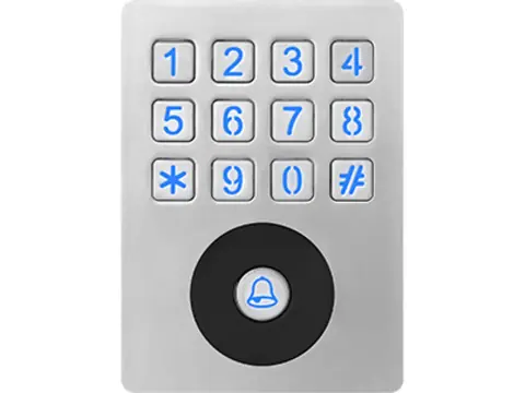
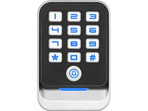
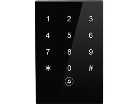
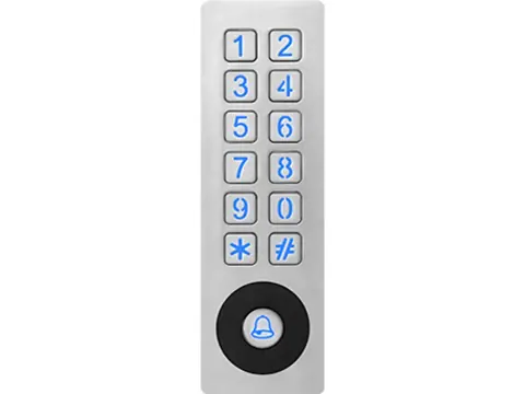
A standalone keypad has its own user memory and relay, so it can control entry without a separate controller. On an egress door, add the complete approved release arrangement; the REX signal alone is insufficient.
Connect it in this order:
- Supply +12V to the keypad’s +12V terminal, and supply GND to the keypad’s GND.
- Jumper +12V to the keypad’s relay COM.
- Keypad NC through the specified egress-release path to maglock +; maglock − back to supply negative.
- Exit button’s NO contact between the keypad’s PUSH terminal (sometimes labeled OPEN or EXIT) and GND.
- Apply only the suppression the exact lock manual specifies, then test every required release path independently of the keypad.
With the relay idle, COM–NC is closed and the lock holds. A valid code or card, or a press of the exit button, energizes the relay for the programmed unlock time; NC opens and the door releases. Check that the keypad’s relay contact rating covers the lock current, especially before adding a second lock. When you compare standalone keypads and exit buttons, check relay ratings, terminal layouts and contact options.
Diagram 2: reader, controller, maglock and power supply
A networked door splits the job: the reader identifies the credential, the controller decides and switches its relay, and the power supply feeds everything.
- Reader: +12V (red), GND (black), D0 (green) and D1 (white) to the controller’s reader port. Most controllers supply reader power from that port. If the reader is powered from elsewhere, its GND must still be tied to the controller’s GND, or the data pulses will not be read reliably.
- Controller: its own +12V and GND from the supply.
- Lock: +12V to relay COM; NC through any release contacts to lock +; lock − to supply GND.
- Exit button: NO contact between PUSH (REX) and GND.
- Door contact: between the door-status input and GND (not drawn).
Run lock power in its own cable where you can. Sharing one multi-conductor cable between lock power and D0/D1 invites the lock’s switching spike into the data lines. A supply with separately fused outputs lets you feed locks and electronics from different outputs, so a shorted lock cable does not take the controller down with it; look for this when comparing access control power supplies.
Diagram 3: interpreting the release path
One possible power-interruption path for a fail-safe lock is:
Battery-backed supply + → dry relay COM → NC → approved release contacts (closed while locked; open to release) → maglock + → maglock − → supply negative
An alternative is the supply’s approved release input switching the relevant lock outputs. A contact’s NC marking describes its de-energized state, not necessarily its healthy or alarm state. Verify the actual contact behavior. Supply interfaces can accept a NC contact, NO contact or specified voltage trigger; never substitute one input type for another.
In the US, sensor-release and door-hardware-release are distinct arrangements. Sensor release can require an approach sensor, an independent labeled manual interruption lasting at least 30 seconds, alarm / sprinkler release and specified power-failure release. Door-hardware release uses the lever or exit device itself to interrupt lock power directly, with separate conditions. An ordinary controller REX input, break-glass device or momentary button alone does not establish either arrangement. Use the adopted code edition and approved release-device instructions to specify the full door.
Where required, alarm and manual release must work with AC absent and the battery connected. Keep logging contacts separate from the power-interruption function. Test sensor or hardware operation, required power failures, release timing and alarm reset / relock behavior before handover.
EN 13637 addresses electrically controlled exit systems in Europe. Any fire-door modification must match the door assembly’s test / certification evidence, including EN 1634-1 where applicable. Listing and system requirements depend on the jurisdiction; UL 294 and UL 1034 are distinct North American standards, not universal proof that an assembled door complies.
Double-door wiring and power-supply sizing
For a pair of doors, fit one lock per leaf (or a double maglock) and wire both in parallel from the same relay output if the leaves must release together. Apply the exact lock manufacturer’s suppression instructions to each lock, and the relay contacts must be rated for the combined current. If they are not, switch the locks through a separate relay module or a power supply output designed for lock switching.
Many dual-voltage locks draw less current at 24 V DC; use their actual ratings rather than assuming an exact half, which also cuts voltage drop on long runs. The lock’s jumper setting and the supply voltage must match.
To size the supply, add up the continuous current of every device at the chosen voltage, taken from each datasheet, then leave headroom; at least 25% is common practice. An example with assumed values: two locks at 0.5 A each, a controller at 0.15 A and two readers at 0.1 A each total 1.35 A. With 25% headroom that is about 1.7 A, so a 2 A load-rated supply covers this operating-load estimate. Check simultaneous peaks, shared charging current and the supply’s limits before selecting 2 A or 3 A. Battery standby adds its own calculation, covered in the power supply sizing guide.
Voltage drop is the other half of sizing. The table shows a 12 V lock drawing 0.5 A at the end of a 30 m (98 ft) cable run, which means 60 m of conductor out and back:
| Wire size | Resistance per conductor | Loop resistance, 30 m run | Voltage drop at 0.5 A | Voltage at the lock (12.0 V supply) |
|---|---|---|---|---|
| 22 AWG (0.33 mm²) | 52.9 Ω/km | 3.17 Ω | 1.59 V | 10.4 V |
| 20 AWG (0.52 mm²) | 33.3 Ω/km | 2.00 Ω | 1.00 V | 11.0 V |
| 18 AWG (0.82 mm²) | 20.9 Ω/km | 1.25 Ω | 0.63 V | 11.4 V |
| 16 AWG (1.31 mm²) | 13.2 Ω/km | 0.79 Ω | 0.40 V | 11.6 V |
Values are illustrative copper conductor resistances at 20 °C; use the selected cable’s specified resistance and installation temperature. Compare the result with the lock’s rated voltage tolerance on its datasheet; lower voltage at the coil means lower holding force.
Wiring an electric drop bolt instead of a maglock
Electric drop bolts use the same terminals, with a few differences:
| Lock type | Relay contacts | State on power loss | Typical supply |
|---|---|---|---|
| Maglock | COM + NC | Unlocked | 12 or 24 V DC |
| Drop bolt, fail-safe | COM + NC | Unlocked | 12 V DC (some 24 V DC) |
| Drop bolt, fail-secure | COM + NO | Locked | 12 V DC (some 24 V DC) |
| Electric strike, fail-secure | COM + NO | Locked from outside; inside lever still opens | 12 or 24 V, AC or DC by model |
- Peak current. A bolt draws more current while it moves than while it holds. Size the supply and cable for the peak figure on the datasheet, and power the bolt from the supply rather than from a controller’s auxiliary output.
- Onboard electronics. Many bolts have a control board with door-position sensing (so the bolt only throws when the door is closed), an adjustable relock delay and a lock-status output. Map door-position and bolt / lock-status outputs to the matching controller inputs; bolt engagement does not necessarily prove that the door is closed.
- Alignment. If the bolt does not line up with its strike plate, it cannot throw fully, and the status output will report the door as unsecured.
When you compare options in the electric bolt locks range, check fail mode, status output and bracket requirements for each door before choosing between a bolt and a maglock.
Suppression: follow the exact lock manual
Inductive loads can produce a switching transient, but lock electronics and suppression differ. Do not add a generic diode or MOV to every maglock. Securitron’s M32/M62/M82B manual explicitly shows a parallel reverse diode as incorrect because it affects quick release. HES specifies a suitable accessory / suppression arrangement for its strikes.
Use the specified component, voltage rating, polarity and location for the exact lock and output. Where a manufacturer calls for a DC flyback diode, its cathode faces positive; reversing it creates a short. A plain diode is not suitable across an AC supply. An arbitrary MOV voltage or a generic 1N4007 recommendation is not a substitute for the equipment instructions.
Troubleshooting: not locking, weak hold, buzzing, residual magnetism
Measure at the lock terminals, under load, before you change anything else.
| Symptom | Likely causes | What to check |
|---|---|---|
| Never locks | No voltage at the lock; lock on NO instead of NC; fire-alarm input open; exit input held low by a shorted cable or a button wired on its NC contact | DC voltage at the lock; relay state; PUSH and fire-alarm inputs |
| Never releases | Lock fed straight from the supply, bypassing the relay; relay contacts welded by unsuppressed back-EMF | Relay click and COM–NC continuity when triggered; suppression at the lock |
| Weak hold | Armature not flat against the lock face; armature fixed rigidly instead of able to pivot; dirt or rust on the faces; low voltage from cable drop; 24 V jumper setting on a 12 V supply | Armature mounting and rubber washers; clean faces; voltage at the lock under load |
| Buzzing or humming | AC or unsmoothed rectified supply; loose armature; failing supply | Confirm the permitted supply waveform; follow armature mounting instructions without clamping out its pivot |
| Door sticks briefly after release | Residual magnetism from a worn or missing anti-residual pin or spacer on the armature; debris; slow decay through a suppression diode | Armature anti-residual feature; clean faces; release time |
| Controller resets or reader glitches when the door releases | Back-EMF; lock power sharing a cable with data; undersized supply | Manufacturer-approved suppression; separate cables; actual peak supply capacity |
Pre-power wiring checklist
- Lock voltage setting and permitted supply waveform match the exact model; confirm polarity and tolerance.
- Dry / powered output type, contact rating and unlock logic checked; NC / NO selected from the actual diagram.
- Only manufacturer-approved suppression used; no added diode on a model that prohibits it.
- Every lock returns to supply GND, and the reader’s GND is common with the controller’s GND.
- REX input wiring distinguished from the accepted independent egress-release arrangement.
- Required manual / hardware / sensor and alarm releases tested on mains and battery, including timing and reset behavior.
- Wire gauge chosen for the run length, with voltage at the lock measured under load.
- Lock power and reader data in separate cables where possible.
- Door contact and lock-status output tested at the controller.
- Required locking-system power failures tested; per-circuit fuse / PTC limits followed without increasing fuse ratings to mask overloads.
Next steps
Send your door schedule (lock type and voltage, number of leaves, controller or keypad, and cable lengths) through our request-a-quote form. We confirm that the maglock, exit button, controller and power supply work together before dispatch, quote within 24 hours, and can send samples for a test door.
Sources
- Securitron M32/M62/M82B installation manual, electrical wiring and quick release; M32/M62/M82 instructions: DC isolation, ratings and monitoring.
- HES 1500/1600 installation instructions and SMART Pac III accessory.
- Altronix ACM manual: output terminals, fire-alarm inputs and fuse ratings.
- ICC: electrical egress-locking arrangements; UL: locking configurations.
- BSI: EN 13637 scope; EN 1634 series.
Frequently asked questions
Does a magnetic lock go on NO or NC?
For a dry relay that is de-energized while locked and energizes to unlock, use COM and NC. Reversed logic changes this. Powered output terminal names can differ, so use the controller or power distribution manual.
How do I wire an exit button to a maglock?
For the illustrated controller input, a NO contact connects PUSH (REX) to GND. That only requests an unlock. For egress, select the required independent release arrangement and approved equipment; a controller timer alone does not provide a direct timed power interruption.
Do I need a diode on a magnetic lock?
Not automatically. Follow the exact lock / output manuals. An added diode can interfere with quick release; other models specify a diode, MOV or dedicated accessory.
Why is my magnetic lock buzzing?
Check the supply waveform and voltage permitted by the lock manual, the armature mounting and the supply under load. Many models need regulated DC; some specifically accept full-wave rectified DC. Do not connect an AC supply unless the exact model permits it.
Why does my maglock hold weakly?
Most often the armature is misaligned, fixed too rigidly to self-align, or dirty, or the voltage at the lock is low because of cable drop or a mismatched 12/24 V jumper. Measure the voltage at the lock terminals under load.
Can two maglocks run from one relay?
Yes, wired in parallel, provided the relay contacts and the power supply are rated for the combined current. Apply the manufacturer's suppression instructions to each lock.
Want a second opinion on your spec?
Send us your controller, credential type and environment — we'll recommend compatible hardware and quote within 24 hours.