Key takeaways
- The four core wires are near-universal: red +12 V DC, black GND, green D0, white D1. LED, beeper and format-select colors vary, so read the reader's label.
- The reader and controller must share a ground, even when the reader runs from its own power supply.
- Plan on stranded, shielded 22 AWG (0.33 mm²) cable and no more than 150 m (500 ft), then check voltage drop on the power pair.
- Ground the cable shield at the controller end only, and keep reader cable away from mains and lock power.
- Swapped D0/D1 inverts every bit, so a controller that checks parity rejects every card.
To wire a Wiegand card reader, connect its red wire to the controller’s +12 V DC reader output, black to GND, green to D0 and white to D1, then connect the LED and beeper wires if the controller drives them. Use stranded, shielded 22 AWG (0.33 mm²) cable, stay within about 150 m (500 ft), and make sure the reader and controller share a common ground. The color chart, two diagrams and troubleshooting table below cover the details that usually hold up an install.
Wire color chart: 12V, GND, D0, D1, LED and beeper
Wiegand is a simple one-way interface. While idle, D0 and D1 both sit at a logic-high level (typically 5 V). The reader sends a 0 by pulling D0 briefly to 0 V and a 1 by pulling D1 low. Those pulses are measured against ground, so the GND wire is part of the signal path, not just the power return.
The four core colors are close to universal. The auxiliary wires are not: the same yellow wire can be a beeper input on one reader and a format-select line on another. Read the label on the pigtail or the datasheet before you terminate anything.
| Function | Most common color | Other colors seen | Lands on (controller) | Notes |
|---|---|---|---|---|
| Power + | Red | — | +12V reader output | Most readers run on 12 V DC; check the rated input range |
| Ground | Black | — | GND | Also the reference for D0 and D1 |
| Data 0 (D0) | Green | — | D0 / DATA0 | Pulses low for each 0 bit |
| Data 1 (D1) | White | — | D1 / DATA1 | Pulses low for each 1 bit |
| LED control | Brown or orange | Gray, blue | LED / GLED output | Usually active-low: pulled to GND = green LED |
| Beeper | Yellow | Purple | BZ / BEEP output | Usually active-low: pulled to GND = beep |
| Format select or hold | Yellow or blue | Varies | Model-specific | Some readers switch to 26-bit output when this wire is tied to GND |
| Shield / drain | Bare or silver | — | GND at controller only | Cut back and insulate at the reader end |
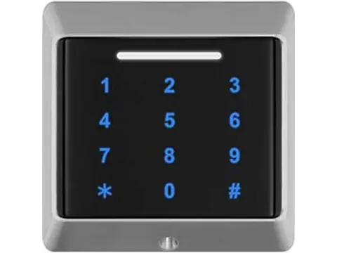
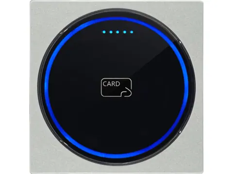
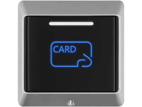
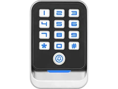
When you order from our Wiegand card and keypad reader range, we confirm the output format against your controller before dispatch. The same signal logic applies to an embedded RFID reader module with Wiegand output, although modules expose pins rather than colored leads.
Diagram: reader to access controller
Most networked door controllers have one reader port per door, with terminals marked +12V, GND, D0, D1, LED and BZ (sometimes BEEP). The wiring is point-to-point:
- Power down the controller before terminating anything.
- Land red on the reader port +12V and black on GND.
- Land green on D0 and white on D1. Don’t assume the terminal order; some controllers put D1 before D0.
- Connect the LED and beeper wires to the matching outputs, or insulate each unused wire separately so it can’t touch its neighbor.
- Connect the cable shield or drain wire to controller GND. At the reader end, cut it back and tape it.
- Set the port to the reader’s output format (26-bit, 34-bit or other), power up, present a card and check the event log.
On the controller side, the LED and beeper outputs are usually open-collector: they pull the reader’s control wire to ground to turn the LED green or sound the beeper when access is granted. If you leave them unconnected, the reader still reads cards; it just gives its default local feedback. When you compare networked door controllers, check the number of reader ports, the Wiegand formats each port accepts and the current each port can supply to a reader.
Diagram: reader as Wiegand input to a standalone keypad
Many standalone keypads accept a Wiegand input, so you can add a second reader without a separate controller. Two layouts are common: an inside exit reader so the keypad logs entry and exit, or a slim vandal-resistant reader outside while the keypad (and its lock relay) sits on the secure side. The second suits exposed doors, because anyone who opens an outdoor keypad has the lock relay within reach.
The external reader is only a front end. The keypad makes the access decision, so three things must line up:
- Mode. Set the keypad to Wiegand input mode if it doesn’t detect the reader automatically. Some models use a menu setting, others a DIP switch.
- Format. The reader’s output (for example 26-bit) must be a format the keypad accepts. A 34-bit reader feeding a 26-bit input is ignored or misread.
- Card numbers. The keypad compares the number it receives with its user list. If a card was enrolled on the keypad’s own antenna, the external reader must report the same number for it, which means the same card technology and the same output format.
Power the reader from the same 12 V DC supply as the keypad and tie all grounds together. The keypad usually doesn’t drive an external reader’s LED or beeper, so insulate those wires unless its manual shows otherwise. When comparing standalone keypads for this layout, confirm Wiegand input support on the datasheet; the standalone keypad programming guide covers switching the input mode and enrolling users.
Cable type, gauge and maximum distance
For most installs, use a stranded multi-conductor cable with an overall foil shield and a drain wire, with 22 AWG (about 0.33 mm²) conductors. Six conductors cover power, ground, D0, D1, LED and beeper; eight leave spares for doubling up the power pair. The industry-standard maximum for a Wiegand reader run is 500 ft (about 150 m) on 22 AWG.
That limit is mostly about the data lines: long cable adds capacitance and picks up noise, which distorts the short Wiegand pulses. The power pair has a separate problem, voltage drop. Reader current flows out on the red wire and back on the black, so the resistance of both conductors counts.
| Conductor size | Loop resistance per 100 m of run | 50 m run, 100 mA reader | 150 m run, 100 mA reader | 150 m run, 200 mA reader |
|---|---|---|---|---|
| 24 AWG (0.20 mm²), typical Cat5e/Cat6 | 16.8 Ω | 0.84 V | 2.5 V | 5.1 V |
| 22 AWG (0.33 mm²) | 10.6 Ω | 0.53 V | 1.6 V | 3.2 V |
| 20 AWG (0.52 mm²) | 6.7 Ω | 0.33 V | 1.0 V | 2.0 V |
| 18 AWG (0.82 mm²) | 4.2 Ω | 0.21 V | 0.63 V | 1.3 V |
Values are for solid copper at 20 °C; stranded and warm cable runs slightly higher. Subtract the drop from the supply voltage and compare the result with the reader’s rated input range. If headroom is thin, double up spare conductors on power and ground (two 22 AWG conductors in parallel behave roughly like one 19 AWG), use heavier power conductors, or power the reader locally as described below.
Cat5e and Cat6 are common on short runs, but they’re unshielded 24 AWG. If you use them, put D0 and D1 on different pairs, pair each with a ground, and double the power conductors. Keep any reader cable away from mains wiring and lock power.
If the run is longer than 150 m, or you need supervised, encrypted reader communication, Wiegand is the wrong interface. RS485-based OSDP runs up to about 1,200 m (4,000 ft), and OSDP v2 with Secure Channel encrypts traffic with AES-128. Our Wiegand vs OSDP comparison covers when to switch.
Power, shared ground and separate supplies
There are two ways to power a Wiegand reader, and both need a shared ground.
From the controller’s reader port. This is the simplest option on short runs. Check that the port’s rated output current covers the reader’s rated current, especially for keypad readers with backlights or multi-technology readers, which typically draw more than a basic proximity reader.
From a local supply near the door. This suits long runs and higher-current readers. Run red and black from the local 12 V DC supply to the reader, run D0, D1 and a ground conductor back to the controller, and connect the local supply’s negative terminal to the controller’s GND. Do not connect the local supply’s positive output to the controller’s +12V; two supplies in parallel fight each other.
Without a common ground, the controller sees D0 and D1 floating relative to its own 0 V. Typical symptoms are no reads at all, or random and wrong card numbers.
If the reader and a lock share one power supply, follow the exact lock / output manufacturer’s suppression instructions and run the lock on its own conductors back to the supply. Do not automatically add a diode: some maglocks prohibit it because it delays release. The voltage spike a maglock or strike coil produces when it switches off can reset a reader or corrupt a read. Size the supply for the reader, controller and lock currents combined, with headroom.
Mounting height and position
- Height. In the US, ADA reach-range rules keep operable parts between 15 in and 48 in (380–1,220 mm) above the finished floor. Centering the reader at about 1,000–1,100 mm (40–43 in) keeps it comfortably inside that range; check local accessibility rules outside the US.
- Position. Mount on the latch side of the door, close to the frame, so users can present a card and push the door in one motion. On narrow aluminum frames, a mullion-format reader fits the profile.
- Metal surfaces. Mounting directly on steel or aluminum reduces read range. Use a non-metallic spacer or a reader specified for metal mounting.
- Back-to-back readers. On thin partitions, offset the inside and outside readers rather than mounting them directly opposite each other; readers that are too close can interfere with each other’s field.
- Cable entry. Bring the cable in from behind, through the wall box, so no reader cable is exposed on the unsecured side. Wiegand data is unencrypted, and exposed D0/D1 wires are an easy place to attach a sniffing device.
- Weather. Outdoors, use a reader with a suitable IP rating, leave a drip loop in the cable and consider a rain cover.
Troubleshooting: no beep, wrong card number, swapped D0/D1
| Symptom | Likely cause | What to check |
|---|---|---|
| No LED, no beep | No power, reversed polarity or blown fuse | DC voltage at the reader terminals with the reader connected |
| Beeps and flashes, but the controller logs nothing | D0/D1 not landed, no common ground, wrong reader port | Continuity of green and white; GND link between supplies; port settings |
| Every card rejected, or parity/format errors logged | D0 and D1 swapped, or 26/34-bit mismatch | Swap green and white; set the port format to match the reader |
| Logged number differs from the number printed on the card | Printed number uses another format, or the reader truncates the ID | Compare facility code and card number, not the long printed number |
| Intermittent reads or random numbers | Noise, shield grounded at both ends (or neither), low voltage | Shield at controller only; separation from lock cable; voltage under load |
| Short read range after mounting | Metal surface or a nearby second reader | Add a spacer; offset back-to-back readers |
| LED stays red after a valid card | LED wire not landed, or LED output not configured | LED terminal; controller LED output setting |
Why swapped D0/D1 rejects every card. Swapping the data wires inverts every bit. In a 26-bit frame, the leading even-parity bit covers itself plus 12 data bits, 13 bits in all. Inverting an odd number of bits turns an even count of 1s into an odd count, so the parity check fails on every card; the trailing odd-parity half fails the same way. The 34-bit format behaves identically, with 17 bits per parity half. Controllers that check parity reject the card; those that don’t log a different number.
Why numbers don’t match. A standard 26-bit frame carries an 8-bit facility code (0–255) and a 16-bit card number (0–65,535), 24 data bits in total. Most card IDs are 32 bits or longer, so the reader drops bits, and which bits it keeps (and in what byte order) varies between reader models. Standardize on one reader type per system, or re-enroll cards when you change readers. The Wiegand 26-bit format guide explains the bit layout and includes a calculator for converting printed numbers.
Commissioning checklist
- Reader rated voltage and current checked against the port or supply rating
- Red, black, green and white landed on +12V, GND, D0 and D1, verified against the reader label
- LED and beeper wires landed or individually insulated
- Common ground confirmed between any separate reader supply and the controller
- Shield or drain connected at the controller end only
- Voltage measured at the reader terminals under load
- Controller port set to the reader’s Wiegand format
- Test card logged with the expected number; LED and beeper respond on a granted read
- Cable entry concealed on the secure side; security screws fitted
Save or print the diagrams
Both diagrams are vector graphics, so they stay sharp when you print this page or save it as a PDF from your browser for a site binder or submittal. For a wiring sheet matched to the reader and controller SKUs on your order, ask when you request a quote.
Next steps
Send us your controller or keypad model, the credential technology on site and your cable run lengths, and we’ll recommend readers with the right Wiegand format and power range. Request a quote for pricing or evaluation samples; we reply within 24 hours.
Suppression source
Only the suppression guidance was reviewed for this update. Securitron SAM installation manual, section 6.3 illustrates manufacturer-specific requirements; use the exact equipment manuals.
Frequently asked questions
What are the standard Wiegand reader wire colors?
Most readers use red for +12 V DC, black for ground, green for D0 and white for D1. LED, beeper and format-select wires vary between models, so confirm them against the reader's label or datasheet.
How far can a Wiegand reader be from the controller?
The industry-standard limit is 500 ft (about 150 m) on 22 AWG shielded cable. For longer runs, move to an RS485-based interface such as OSDP, and check voltage drop on the power pair at any length.
Can I use Cat5e or Cat6 cable for a Wiegand reader?
It works on short runs, but it is unshielded 24 AWG, so noise and voltage drop limit the distance. Put D0 and D1 on separate pairs, pair each with a ground conductor, and double up the conductors used for power.
What happens if D0 and D1 are swapped?
Every bit arrives inverted. On 26-bit and 34-bit frames that always breaks the parity check, so most controllers ignore the card; controllers that skip parity checking log a different number.
Do I need a common ground if the reader has its own power supply?
Yes. D0 and D1 are measured against ground, so the reader supply's negative terminal must connect to the controller's GND. Never connect the positive outputs of two supplies together.
How high should an access control card reader be mounted?
In the US, ADA reach-range rules keep operable parts between 15 in and 48 in (380–1,220 mm) above the finished floor. Centering the reader at about 1,000–1,100 mm (40–43 in) sits comfortably inside that range; follow local accessibility rules elsewhere.
Want a second opinion on your spec?
Send us your controller, credential type and environment — we'll recommend compatible hardware and quote within 24 hours.