Key takeaways
- The reader chip sets the ceiling for inventory speed, receiver behavior and power per read; the module's amplifier, filtering and firmware set most of what you measure.
- Both platforms can reach the legal radiated-power limit, so with the same antenna, cable and tags they read about as far.
- E710-class modules are the newer generation and are usually specified with higher tag throughput and lower current at a given output power.
- R2000-class modules remain a mature, well-understood choice, especially when host software already exists for them.
- Changing platforms is a software and certification project: the UART command set belongs to the module firmware, and the finished device needs its own approvals.
Impinj® E710 vs R2000 is mostly a choice about throughput, power draw and software, not read range. Both chip platforms can drive a module to the legal radiated-power limit, so with the same antenna, cable and tags they read about as far. E710-class modules are the newer generation and are usually specified with faster inventory and lower current at a given output, while R2000-class modules bring a long field record and existing host software.
Impinj, Indy and related names are trademarks of Impinj, Inc. We use them only to identify chip platforms and are not affiliated with Impinj.
What the reader chip decides
A UHF reader module is more than its chip. Around the reader IC sit a power amplifier stage (on-chip or external, depending on the design), transmit and receive filtering, a coupler that lets one antenna port transmit and receive at the same time, a microcontroller running the module maker’s firmware, supply regulation and one or more antenna ports. “E710 module” or “R2000 module” describes one part of that stack.
The chip sets the ceiling in three areas:
- Protocol engine. How quickly it runs EPC Gen2 (ISO/IEC 18000-63) inventory rounds, and which link profiles it supports. The standard allows Tari values from 6.25 to 25 µs, backscatter link frequencies from 40 to 640 kHz and FM0 or Miller (M = 2, 4, 8) encoding; each chip implements a set of profiles within those limits.
- Receiver behavior. How well it recovers weak tag replies while its own carrier leaks back from the antenna (the self-jammer).
- Power per read. How much supply current the RF and digital sections need at a given output, which drives battery life and heat.
The module sets most of what you measure on the bench: output range and flatness, real sensitivity at the antenna port, port count, command set, region tables, supply range and the thermal path. Two modules on the same chip can behave very differently.
The Indy R2000 has been in volume use for more than a decade. The E710 belongs to Impinj’s E-series, released roughly ten years later, which also includes parts such as the E310, E510 and E910 at other performance and power levels. Some listings use “R2000” loosely, so ask which reader IC is on the board and request the module’s own datasheet. Browse our UHF reader modules and we will confirm the reader IC for any module you shortlist.
Comparison table: output power, sensitivity, speed, current draw
A module’s numbers depend on its amplifier, filters, firmware and supply, not just the chip. The table therefore shows typical module-level ratings and what to check, rather than chip headline figures.
| Parameter (unit) | R2000-class module | E710-class module | What to check |
|---|---|---|---|
| Platform maturity | In volume use for more than a decade | Newer generation, released about ten years later | Lifecycle status and supply over your production horizon |
| Max conducted output (dBm) | Commonly 30–33 dBm (1–2 W) | Commonly 30–33 dBm (1–2 W) | Output measured at the port, at your supply voltage and temperature |
| Receiver sensitivity (dBm) | Quoted per module | Quoted per module | Output level, antenna return loss and link profile during the test |
| Peak inventory rate (tags/s) | Typically quoted in the hundreds of tags/s | Usually quoted higher than comparable R2000-class designs | Rate with your tags, population and link profile |
| Supply (V DC) | Single rail, roughly 3.3–5.5 V depending on the module | Single rail, roughly 3.3–5.5 V depending on the module | Exact range, ripple tolerance and brownout behavior |
| Current at full output (A) | Often 1–2.5 A peak | Usually lower at the same output | Peak and average current, measured on an oscilloscope |
| Heat at full output | Heatsink or metal-chassis contact usually required | Less heat at equal output in most designs; still needs a thermal path | Temperature rise at your duty cycle and worst-case ambient |
| Air protocol | EPC Gen2 (ISO/IEC 18000-63); some add ISO 18000-6B (now ISO/IEC 18000-62) | EPC Gen2 (ISO/IEC 18000-63) | Gen2v2 commands, 18000-6B and vendor extensions, per firmware |
Why read range is not in the table. The chip does not set it. In most passive-tag deployments the forward link runs out first: the tag stops getting enough power to wake up before the reader stops hearing it. Radiated power is capped by regulation, so with equal antennas, cables and tags, both platforms reach similar distances. Receiver quality matters more with very sensitive tags, poor antenna match or many readers nearby. Our UHF read range guide walks through the link budget.
Speed claims need context. Peak tags-per-second figures are usually measured with a fast link profile, a modest tag population and a single reader. Real throughput depends on the link profile, the Q (anti-collision) algorithm, Gen2 session and target settings, and how many readers share the site. Dense-reader profiles use Miller encoding to keep tag replies away from neighboring readers’ carriers, trading speed for reliability. For large populations at dock doors or conveyors, test with your own tags; that is where the newer platform tends to show its advantage.
Current and heat go together. At 30–33 dBm the amplifier turns several watts of supply power into heat, and the current step at carrier switch-on can pull an undersized rail low enough to reset the module or host.
Module integration: UART, power supply, heat and antenna matching
UART and command set. Most modules expose a TTL UART at 3.3 V logic, commonly defaulting to 115200 bit/s. Check 5 V tolerance before connecting a 5 V microcontroller, and add an RS232 or RS485 transceiver if the link leaves the board. The command set belongs to the module maker’s firmware, not the chip, so an E710-class module will rarely drop into host code written for an R2000-class module without changes.
Before you commit, ask for the full protocol document and check:
- Polled versus continuous (autonomous) inventory modes
- Tag report fields (EPC, PC word, RSSI, antenna port) and buffer depth
- Error codes, timeouts and how settings persist through power cycles
- The firmware update path over UART
Power supply. Size the rail for peak transmit current, not idle current, and put low-ESR bulk capacitance close to the module so the voltage holds when the carrier turns on. Ripple and switching noise on the supply can show up as spurious emissions and raise the receiver’s noise floor, so filter a switching regulator’s output or feed the module from a clean dedicated rail. On battery devices, confirm the cell and its protection circuit can deliver peak current when cold and nearly empty.
Heat. Give a high-power module a real thermal path: a heatsink, or a thermal pad onto a metal chassis. In a sealed plastic box at full power a module can overheat, and some firmware lowers output or stops transmitting at an internal temperature limit. Measure temperature rise at your real duty cycle and worst-case ambient; every dB of output you do not need is heat you do not have to remove.
Antenna matching. Module antenna ports are 50 Ω, and most modules are monostatic: one port transmits and receives. Power reflected by a mismatched antenna therefore lands in the receiver as extra self-jammer and cuts effective sensitivity. Many designs target a VSWR of 1.5:1 or better (a return loss of about 14 dB); check it with the antenna in its final position, because nearby metal and the enclosure detune it.
Cable loss counts twice, once on the way out and once on the way back, and 3 dB of loss halves the power reaching the antenna. Keep coax short, use low-loss cable for longer runs, and note that miniature board connectors are rated for few mating cycles. Multi-port modules switch one transmitter between ports in turn, adding insertion loss. Choose the antenna for the read zone from our UHF antennas, from compact ceramic and PCB designs to circular-polarized panels.
Choosing by device type
| Device type | Typical conducted output | Antenna ports | Platform leaning | Main design constraint |
|---|---|---|---|---|
| Handheld reader or RFID sled | Up to about 30 dBm, often run lower | 1 | E710-class or another low-power platform | Battery peak current, heat in a sealed housing, RF exposure near the body |
| Fixed portal, dock door or conveyor | Set to the regional limit after cable loss | 4–8, multiplexed | E710-class for high tag counts; R2000-class for moderate counts | Throughput, dense-reader operation, cable and switch loss |
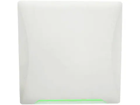
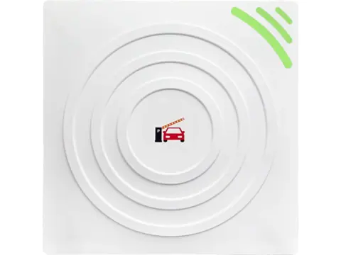
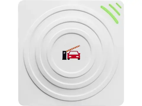
| Integrated long-range reader (parking, gates) | Reduced as antenna gain rises, to stay within EIRP limits | 1 | Either; R2000-class is widely used | EIRP compliance with a built-in antenna, outdoor temperature range |
| Smart cabinet, shelf or tool crib | Low to medium | 4–8, or more with external switching | Either | Near-field antennas and reading only the intended zone |
| Desktop encoder or card issuer | Low, for a short and controlled read zone | 1 | Either, or a low-power platform | Avoiding reads of neighboring tags |
| Battery-powered embedded device | Low, roughly 18–26 dBm class | 1 | Low-power single-chip readers | Sleep current and peak current from a small cell |
Lean toward an E710-class module when:
- The device runs on a battery, or the enclosure has little room for a heatsink
- Many tags must be read in a short window, such as cartons on a pallet
- You are writing host software from scratch and want the longest platform life
An R2000-class module is still a reasonable pick when:
- Your host software already speaks an R2000-class command set
- Tag counts per read are modest, as in vehicle access or single-item reads
- Mains power and space for a heatsink are available
If your device also needs to read 13.56 MHz NFC cards or 125 kHz fobs, pair the UHF module with an LF or HF module from our RFID reader modules range. If a finished reader suits you better than a module, see how to choose a UHF RFID reader.
Region bands and end-device certification
Reader chips cover the worldwide UHF RFID bands, but modules are filtered and configured for a band and are often sold as regional versions. Order the version for the destination market and check its firmware channel table.
- FCC, 902–928 MHz: frequency hopping, up to 1 W (30 dBm) conducted and 4 W (36 dBm) EIRP; above 6 dBi of antenna gain, conducted power drops 1 dB for every extra dB. A 33 dBm setting is not a legal US setting.
- ETSI EN 302 208, 865–868 MHz: four high-power channels at 865.7, 866.3, 866.9 and 867.5 MHz, up to 2 W ERP (about 35.15 dBm EIRP).
- Other markets use their own sub-bands and limits; see our UHF frequency by country guide before you fix a SKU.
Output above 30 dBm is headroom for regions and installations that allow it, not a default. Lock region and maximum output in firmware: FCC rules (47 CFR §15.15(b)) prohibit user controls that let a device operate outside its authorized parameters.
The module’s approvals help, but the finished device is what gets certified:
- United States. A module with a modular grant (§15.212) can be integrated without recertifying the transmitter if you follow the grant’s conditions, such as approved antennas and the “Contains FCC ID” label. The host still needs Part 15 Subpart B evaluation. Handheld designs used within 20 cm of the body typically need an RF exposure (SAR) assessment; mobile and fixed installations use MPE distance calculations.
- European Union. Under the Radio Equipment Directive (2014/53/EU), the company placing the finished product on the market signs the Declaration of Conformity. Commonly applied standards include EN 302 208 (radio), EN 301 489-1 and -3 (EMC), EN 62368-1 (safety) and EN 50364 (human exposure). If the product can connect to the internet, the RED cybersecurity requirements that apply from 1 August 2025 also cover it.
- Elsewhere. Canada (ISED), the UK (UKCA) and most Asian markets run their own schemes; budget time for each.
Our embedded RFID module checklist covers device-level certification in more detail.
Dev kits and sampling
A typical development kit includes the module on a carrier board, a USB-to-UART bridge, a power adapter, an antenna, sample tags, PC demo software and the protocol document, plus an SDK where one exists. Use it to learn the command set, then validate samples in your own hardware:
- Read performance: your tags, mounting surface, orientations, antenna and cable.
- Current profile: peak and average current on an oscilloscope as the carrier switches.
- Thermal behavior: continuous inventory in the final enclosure at worst-case ambient.
- Region settings: channel table and maximum output for each target market.
- Software effort: port a slice of host code to the command set and time it.
If you are undecided, sample one module of each platform and run the same tests side by side. Your own enclosure and tags will settle the question faster than any datasheet.
Platform selection checklist
- Tag population per read zone and the time available to read it
- Target regions and the maximum conducted output allowed in each
- Antenna type, gain, cable length and loss budgeted per port
- Supply rail sized for peak current, with bulk capacitance at the module
- Thermal path designed for full output at worst-case ambient
- UART voltage levels, baud rate and protocol document confirmed
- Compatibility with existing host software checked, or porting effort estimated
- Reader IC confirmed on the module’s own datasheet
- Lifecycle and long-term supply confirmed for your production horizon
- Certification route planned for each market
- Samples tested in the final enclosure with real tags
Next steps
Send your device type, target regions, tag population and host interface through our request-a-quote form. We confirm the reader IC and regional version for each module we shortlist, test samples before dispatch, and quote within 24 hours.
Frequently asked questions
Is the Impinj E710 better than the R2000?
For new designs, E710-class modules are usually specified with faster inventory and lower current at the same output power. The R2000 generation is still a sound choice for modest tag counts or when host software for an R2000-class module already exists.
Will an E710 module read farther than an R2000 module?
Not by itself. Regulations cap radiated power and passive-tag range is usually limited by how much power reaches the tag, so with the same antenna, cable and tags the two platforms reach similar distances.
Can I swap an R2000 module for an E710 module without changing my software?
Usually not. The command set is defined by the module maker's firmware rather than the chip, and the pinout, supply range and connector can differ too, so plan for host code changes and new tests.
Can I run a 33 dBm UHF module at full power in the United States?
No. FCC Part 15 limits 902–928 MHz readers to 1 W (30 dBm) conducted and 4 W (36 dBm) EIRP, with conducted power reduced dB for dB above 6 dBi of antenna gain. Lock the maximum output in your firmware for each region.
Why does my UHF reader module get hot?
At 30–33 dBm the power amplifier turns several watts of supply power into heat. Give the module a heatsink or a thermal pad onto a metal chassis, and reduce output power or transmit duty cycle where the application allows.
Does a module with its own approvals make my product compliant?
It helps but does not finish the job. The finished device still needs evaluation, for example FCC Part 15 host testing and labeling, and in the EU the company placing it on the market signs the Declaration of Conformity under the Radio Equipment Directive.
Want a second opinion on your spec?
Send us your controller, credential type and environment — we'll recommend compatible hardware and quote within 24 hours.